Real Digital Twin divided in different layers
- Project
- 19027 AIToC
- Type
- New product
- Description
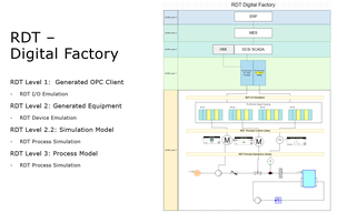
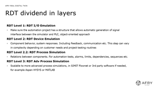
We have divided our solution into different levels and functionality of an RDT depending on the customer or project goals. The testbed is divided into three layers: • I/O emulation/Electro-hydraulic model • Hardware simulation • Process simulation
- Contact
- Andreas Buhlin
- andreas.buhlin@afry.com
- Research area(s)
- .
- Technical features
3.1 RDT Level 1: I/O emulation (Electro-Hydraulic model) The electro-hydraulic model is defined by a connection table in the project specification. It is a model of all connections between terminals and automation hardware such as frequency converters, sensors, and valves. This layer in the simulator separates I/O from equipment and allows the hardware model and process model to remain locked and unchanged for future updates to the control system. Only the Electro-Hydraulic model needs to be updated.
3.2 RDT Level 2: Device Emulation (Hardware) The hardware model is defined by a component list according to the format of the project specification. The hardware simulation reads control signals from the control system via the Electro-Hydraulic model, measures process values from the process model and provides feedback to the control system inputs via the Electro-Hydraulic model.
3.3 RDT Level 3: Process Simulation Without a process model, we only have static values on sensors and transmitters. To run sequences in the control system, we would then need to set sensor and transmitter values manually to step through the sequence. The main purpose of the process model is not to realistically model the process, but to obtain process values for transmitters and sensors needed to run sequences from the control system.
- Integration constraints
.
- Targeted customer(s)
All industries using a control system (PLC)
- Conditions for reuse
Licence
- Confidentiality
- Public
- Publication date
- 29-01-2024
- Involved partners
- ÅF-Industry AB (SWE)
Images


